−Table of Contents
Welcome to my 3D Printer wiki
My latest project
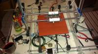
A 3D Printer using Open Source , Linux and no 3D printed parts.
First of all why make my own printer using only parts from the Hardware. First of all I don't have another printer to make the parts, so any person no matter where he lives and duplicate it.if the build comes out right then it was worth it.
A 3D printer is composed of a 3 axis movement system, the 3 axis are controlled by stepper motors. There is also an extruder to lay the hot plastic and a heated plate to keep the first layer hot in order to be able to extract the object.
Doing the research for my printer I found out how cryptic all the instructions are, most sites assume you know what they are talking about so I decided to build my own with parts that I have available and whatever I can't build then I will purchase.
I am writing this as a wiki because I will document all the steps of the build in case I forget or someone wants to follow my build.
The first thing I had to get are the threaded rods from the hardware store and some 1/4 inch Lexan plastic. I also had a plastic that measured 3/4 inch by 3 inch by 18 inches that I am going to use to tie the threaded rods together, the threaded rod are 5/16 inch by 18 inches , they where the only ones they had in that length.
===== Starting October 1 2014 I will be making another 3D Printer, this time I will be using the 80/20 inc. 10 Series - 1.00“ increments and a .50” Centerline square tubes. This will make the printer more rigid.
Go to 3D Printer Blog and check it out.
Contact me at ralcocer@rafaelalcocer.com
The Learning Starts
Getting Started with 3D Printing
http://www.makerbot.com/support/guides/design/, Getting started with 3d Printers
http://www.popularmechanics.com/technology/how-to/tips/how-to-get-started-3d-modeling-and-printing, Popular Mechanics
http://bukobot.com/getting-started-with-3d-printing, Bukobot
As you can see from the above links 3D printing is not as easy as it seems there a a lot of different software programs and hardware that has to work in order to print, I am still learning, so here is how I started.
3-D Drawing or CAD (computer aided design)
BTW: My linux distribution is Porteus, http://porteus.org, it is based on Slax which in turn is based on Slackware which is the oldest Linux distribution. Slax is the live-cd for Slackware. I run my Linux as a live distribution running from my USB pen drive. Every time I want to try a new program I make a new module activate it and if it works I copy it to my pen drive. If I want to copy the module to my Hard Disk I just copy paste it.
There is a lot of of software out there that works in Windows , for Linux you have choices also, I decided to use Blender, http://www.blender.org/, it's easy to use just decompress it and click on the blender file and it runs.
I don't do graphics that well, I am a Hardware person and I do programming but no Graphics, for now I will put that aside and work with pre-made projects from Thingiverse http://www.thingiverse.com/, there are lots of thing to print in there.
There are some Web-Based Cad Software some work in linux others, no, I tried https://tinkercad.com/ Tinkercad, on line CAD software to see if It loaded and it did, so much for that.
The STL files
Ok so in order to print you must have a files that end with a .stl, from “STereoLitography” - the format was actually developed for feeding 3D printers.
STL files are an open file standard and are widely used in Computer Aided Manufacturing (CAM) and rapid prototyping. The STL file format is good for printing out parts because it describes a part's surface geometry.
Wikipedia has a better than mine,http://en.wikipedia.org/wiki/STL_(file_format)
B-code
The Tool Chain
 As you can see from the flow chart you need to convert the .stl file from the CAD applications to a format the printer understand, the printer deposits(extrudes) plastic in slices to the platform, so we must get a slicer program to do the work or we can get an integrated program that will do thet for us, there is one integrated program named Replicatorg, http://replicat.org/
The Hardware
The hardware you need for the printer is as follows;
1x Thermistor 100K
5x NEMA17 Stepper motor 1.8 degrees step / 4.8 kg/cm (4 for the XYZ axis and one for the extruder)
1x RAMPS 2560 Electronics - Atmega 2560 (Arduino-compatible)
1x RAMPS - Fully assembled v1.4
4x Stepstick A4988
1x Heatsinks for pololu / stepstick stepper drivers (set of 4)
3x Miniature microswitch
1x Wire wound power resistor,6R8 2.5W
I found everything in Ebay, the Atmega I got cost me $14.00 from China and it even have the Arduino markings. RepRap Arduino Mega Pololu Shield, or RAMPS for short. It is designed to fit the entire electronics needed for a RepRap in one small package for low cost.
The modular design includes plug in stepper drivers and extruder control electronics on an Arduino MEGA shield for easy service, part replacement, upgrade-ability and expansion. Additionally as long as the main RAMPS board is kept to the top of the stack a number of Arduino expansion boards can be added to the system.
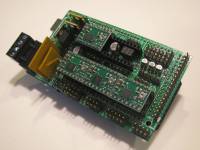 This is what it looks like. I purchased the motor-contol boards from Botronicz at ebay,http://www.ebay.com/itm/StepStick-5pcs-A4988-Stepper-Driver-Reprap-Prusa-Mendel-Sanguinololu-RAMPS-/140967386673?pt=LH_DefaultDomain_0&hash=item20d24f9e31, http://www.botronicz.com/, they are good company to deal with.
This is the wiring for the printer.
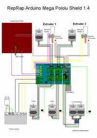
Jumper for the Ramps board. 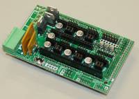 Stepper Driver Boards
Jumpers need to be installed under each stepper driver:
jumper Yes/No step size
1 2 3
no no no full step
yes no no half step
no yes no 1/4 step
yes yes no 1/8 step
yes yes yes 1/16 step
For now the default is 1/16 micro stepping (all jumpers installed under drivers)
Cut the pin headers to 8 pins long so that they fit each side of the stepper driver.
Insert the pin headers into the sockets on RAMPS
Fit the stepper drivers onto the pin headers and solder. Only heat each pin for a few seconds at time to avoid damage to the socket.
Glue the heatsink (if used) to the top of the A4988/A4983 chip using the provided pad of double-sided adhesive.
Mechanical Endstops
The recommended firmwares provide a configuration to use mechanical endstops with just these two wires.
Connect GND on RAMPS to C on the switch. Connect S on RAMPS to NC on the switch.
Put the connectors on the motor wires
solder a female connector to the ends of each wire.
use the 2.54mm 1×3 housing.
mechanical endstops (now the default ultimachine.com option) require #define OPTO_PULLUPS_INTERNAL 1 to be added to configuration.h
There are predefined pins for FiveD_on_Arduino in git master, but support is experimental. Programming works following the instructions in the wikipage.
Thermistor Wires
Use a 2 pin 0.1“ connector to terminate the thermistor wires. Connect the cable so the 2 wires go to T0 Connect the 2 heater wires to D10 (E0H on older boards) and the + connection above it. If changing to an unverified firmware it is best to verify heater circuit function with a meter before connecting heater to prevent damage to the extruder.
Connecting Power
Connect your 12V power supply to the RAMPS shield.Reversing +/- or otherwise incorrectly connecting power can destroy your electronics and cause fire hazard The bottom pair of connectors marked 5A power the stepper drivers and Extruder heater/fan (D9,D10). The power supplied to these should be rated a minimum of 5A.
The pair of connectors above marked 11A power a Heated Bed, or other output (D11). The power supplied here should be rated a minimum 11A. (If both power rails are connected to the same supply it should have a minimum rating of 16A) The barrel connector (DC power input) on the Arduino MEGA itself is not used for our application. The power connector plug may not be obviously labeled, looking at the power connection the positive is on the left and the negative is on the right of the plug.
Maximum Input Voltage
Power Supply without diode The 1N4004 diode connects the RAMPS input voltage to the MEGA. If your board does not have this diode soldered in, you can safely input as much as 35V. (The pololus can do up to 35V)
Power Supply with diode
If your board has a 1N4004 diode soldered in, do not apply more than 12 V to it. Original flavor Arduino Mega are rated to 12 V input. While Arduino Mega 2560 can take 20 V, it is not recommended.
The Software
Install the required packages (gcc-avr, avr-libc, etc.)
The Firmware
Sprinter-Firmware https://github.com/kliment/Sprinter
Tea-Cup-Firmware http://reprap.org/wiki/Teacup_Firmware, Teacup avoids C++ in
favour of plain C, uses 100% integer math and works
very hard to minimize/eliminate long math operations in interrupt context.
As a result, it offers optimum precision over a wider range
(integer = 31 bit, float = 23 bit), it's only half the binary size of
similarly featured firmwares, runs on about any ATmega microcontroller
existing, including the USB-equipped ones, and can still be tailored to
run on controllers as small as the ATmega168.
Repetier-Firmware http://reprap.org/wiki/Repetier-Firmware
Repetier-Firmware is a firmware for RepRap like 3d-printer powered with an Arduino compatible controller.
This firmware is a nearly complete rewrite of the sprinter firmware by kliment which based on Tonokip RepRap
firmware rewrite based off of Hydra-mmm firmware.kept the sprinter logic as far intact as possible.
As a result, all boards with at least 64kB RAM working with Sprinter should work with this firmware.
This includes Sanguino/GEN 6/Gen 7/Mega/RAMPS/ Teensylu/Printrboard Boards.
So far I have tested Tea-Cup and Sprinter with the Arduino and I am still to try them with the stepper motors.
Pronterface, Pronsole, and Printcore - Pure Python 3d printing host software runs in Linux also.
There is another software that I compiled but other than running it I have not done anything else the name is CURA http://wiki.ultimaker.com/Cura, I compiled it because it runs in Mono which is like running Windows and I have never used it.
Cura is developed by Ultimaker to make 3D printing as easy and streamlined as possible.
It includes everything you need to prepare a 3D file for printing and to print it.
Cura is fully preconfigured to work on the Ultimaker.
Cura comes with a friendly setup program that help you install the
latest firmware as well as calibrate your printer.
ReplicatorGhttp://replicat.org/, is a simple, open source 3D printing program
This is the software that will drive MakerBot Replicator, Thing-O-Matic, CupCake CNC, RepRap machine, or generic CNC machine.
You can give it a GCode or STL file to process, and it takes it from there. It's cross platform, easily installed, and is based on
Arduino and Processing environments.
Marlin 3D Printer Firmware
Derived from Sprinter and Grbl by Erik van der Zalm. Marlin 3D Printer Firmware
More information can be found here:
The Power
ATX Power Supply Source
Putting it all together
http://www.reprap.org/wiki/Stepper_wiring, Wiring Stepper Motors
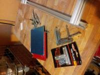
Yow will need 8 of this 8020 T Slot Aluminum Extrusion 10 S 1010 x 12 N, you can buy the 24 inch long if you want to increase the size of the printed area.
8020 T Slot Hardware FBHSCS & T Nuts 10 S 3384 (25pc) N, you will nead at least 50 of this maybe more if you want to put a screw in every hole.
2 x 8mm 300mm 12" Hardened Shafts with 4 LM8UU Rod Rail Linear Motion 3D Printer you will need 3 of this shafts.
5pcs - Flexible Coupler 5 x 8 mm for 3D Printer Z Axis NEMA17 RepRap Mendel
3D Printer 0.4mm Extruder Nozzle Print Head for MK8 Makerbot RepRap
3D printer collection , here are all the parts needed for a printer in one page.
The J-Head Lite V2 Ultimate Economy RepRap 3D Printer Hot End For 1.75mm ABS/PLA, if you want to use a J-head this will work however you will not use the J-head in my printer.
Extruder
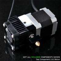 This is the extruder I will be using , I got it from QU-BD, .
I purchased it as a kit and it was quite simple to assemble. My next step is to finish the X and Y movements, I will be starting with the Z because that is where the Extruder is mounted. I also have to figure out how to mount another stepper motor to move the X drive , the other thing I have to solve is that the belts and the pulleys I have don't match, so I will work in getting the hardware to work and solve the pitch problem later.
The first problem I encountered was that the extruder will jam and you will have to stop and disassemble the extruder. I found this page Slic3r: Strange Defaults causing QU-BD woes, which deal with the Slic3r program, It's not an easy program to setup if you don't know what everything is, however after many months of frustration, I finally decided to order one of the fixes there are in Thingiverse. My first option was the QUBD extruder mod, the problem that I had was that the heat from the extruder and the ambient temperature made the arm with the bearing to bend out of shape do to the heat and it also jammed. So I still have a problem with the extruder. After a few months talking to the person who sold me the modification, I gave up and though of quitting the project, after a week I decided to give it another shot.
So I decided to try to calibrate the extruder, I knew it was jamming but to do that I separate the heated-end and the extruder separately so I could get to temperature and let Pronterface run, as soon as I did that the filament started coming out and the amount measured was way more than It was set in the program, now I know why the extruder jams, there is to much filament coming out of the extruder to the heated-enf and of course it jams.
So I started to play with the extruder and when measuring the filament I found that if I wanted 10mm I got 100mm of filament so it meant that the extruder was extruding 10 times the ammount of filament, no wonder the extruder was choking, now I have to find where to make the changes.
There is the software and the firmware to deal when printing in 3D and they each interact, so to get the setting right I went to the Prusa calculator, it's generic but it calculates most of the setting you need, only problem is where do you make the changes. You can use Pronterface to make some of the changes.
I found several calculators to calibrate the extruder, here are some: Tantillus, This calculator is for modified Tantillus, different machines or just going deep into the variables.
How to calibrate the Extruder on your 3d Printer
Stepper Motors Calculates the steps in the stepper motors and other useful settings. It turns out that the changes are in Marlin and in just one line and that is to change the default settings in all the stepper motors.
Belts, Pulleys and Stepper Motors
E-Bay has the stepper motors 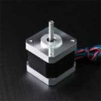 , pulleys and belts. Here is a rundown on theTiming Belts . When I get to that point I will order from them the stepper motor , belt and pulley since I know I won't find them locally.
There is a good explanation of the StepStik-A4988 stepper motor controller at http://www.pololu.com/catalog/product/1182, Pololu and a good explanation on how to connect your Stepper motor, these are very important because if done wrong I can fry all the electronics. Ebay is also a good place to purchase the motors and maybe you can get better prices especially if they are from China.
You will also need the wiring plugs and pins, E bay is the best place to look for the . Prusa Mendel wires. You can buy almost everything from this Prusa search in E-bay.
I chose to use the GT2 20Teeth Pulleys and the GT2 Timing Belt from E-Bay this item gives you enough belt and pulleys for the X and Y axis.
Adjusting the Stepper Controller
Tuning motor current
Per the A4988 datasheet, the calculation for the maximum trip current is: I_TripMax= Vref/(8*Rs) With Pololus, the sensing resistors are Rs=0.05 ohm, so a Vref of 0.4 should produce a maximum current of 0.4/(8*0.05)=1A. Clockwise increases the current which will make the motor run hotter and counterclockwise reduces it which will cool it down (see forum thread 159081). As another example, aiming for 50% temperature rise on 1A rated steppers by using max 0.7A, so rearrange it as: Vref = I_TripMax * 8 * Rs or Vref = 0.7 * 8 * 0.05 = 0.280V With a measured Vref of 0.273V, I should expect 0.6825A, and I measured the current through one coil as 0.486A in full step mode, which should be 0.7071 of the full trip current, or I_TripMax= 0.486/0.7071= 0.687A, which seems close enough. The Vref signal is accessible as the “VREF” pin on the carriers with voltage regulators, as the through-hole via on the carriers without, and also as the wiper on the trim pot itself on both carriers.
example of a v-ref checking, + probe on the turnpot and - on a ground pin Note: for StepStick, the Rs=0.2 ohm, so you'd get 4 times the Vref at the same current. Note 2: for DRV8825, the current sense resistors are 0.1Ω. The calculation changes to “Current Limit = VREF × 2”, or “VREF = Current Limit / 2”. The maths in full
For repraps, logic supply voltage (VDD) is 5V. For Pololu driver boards, the trimpot is 100kohm, R5 resistor is 20kohm, sense resistors R7 and R8 are 0.05ohm VREF max = (TrimpotMaxR/(TrimpotMaXR+R5)) x VDD = (100,000 / (100,000 + 20,000)) * 5 = 4.16V ITripMAX (effectively max motor current) = VREF / ( 8 x Sense_resistor) = 4.16 / ( 8 * 0.05 ) = 10.4A To calculate amps from measured VREF: A = VREF / 0.4 To calculate VREF required for a target current: VREF = A * 0.4
More information here reprap.orgPololu stepper driver board
Heated Bed
X axis
Y axis
Z axis movement
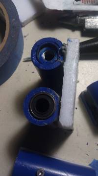
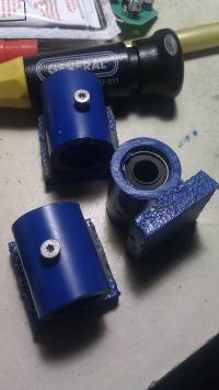
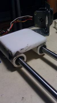
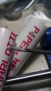
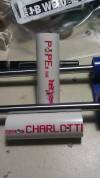 I was trying to meke the Z axis movement, this is the movement that has the heated extruder, I already had the linear bearings but needed something I could put the bearings in looking arount I fount a 1.2 inch PVC pipe end tried to fit the bearinh in it and it fit perfectly. So my next step was to dill a two holes and tapp then so I could put a screw to secure the bearing.
To make it clear I have never seen a 3D Printer at work, I saw a printer at Tech-shop in San Jose but it was off, the rest is what I have seen on YouTube and other websites, I have seen all the calibration and assembly videos there are
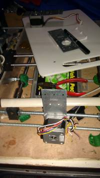
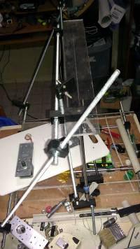
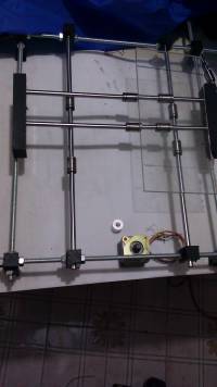
My first build was a _Prusa mendel printer, the parts needed for the basic build are threaded rods and nuts, when I went to the Hardware store they had abot 30 5/8 x 18 inches rods at .50 cents each so I grabbed them. I also found some Sliding Door rollers , more like bearings so I grabbed a pack of 4 too. Now I have to wait for the smooth rods and the linear bearings I ordered in June 19, 2013.
